Atari 5200 Flex Circuit Upgrade project!
Since Best started the Atari CX52 Joysticks upgrade Gold project in 2005, one of the components in the CX52 Gold upgrade parts that has always been a headache, had a lot of process problems and prices have continued to go up in cost for the last 16+ years, is the stock Atari made 1982 Rev. 9 tin plated internal flex circuits Gold plating process. Because of the very high costs of the Gold plating process, Best always did small lots of 100 or less of the Atari CX52 Rev. 9 flex circuits batches. Basically living hand to mouth and occasionally selling out of them temporally.
Every time we sent a batch of old / new Atari CX52 joystick Rev. 9 flex circuits out for the Gold plating process, we would never know if this process would go well or end with either damaging flex circuits or a complete lot failure (scrap out a lot of new rev. 9 flex circuits). The Gold Flex Circuit is just one of the critical internal components (one half of a mechanical switch) on an Atari CX52 Joystick. The new Best Rev. 10 Upgraded / Enhanced CX52 Gold Joystick flex circuit by itself will possibly extend the usable life of an old carbon dot (depending on the exact failure mode of the 30+ year old carbon dot internal pads) Atari 5200 Joystick. But it is not the final answer to a lifetime Atari CX52 Joystick. It must be used with the Best upgraded Gold dot 2nd Gen. Tactical fire buttons, Best CX52 Gold dot Aux. pad (Start, Pause, Reset) and the Best 2nd Gen. Tactical Gold dot numeric keypad to reach an Atari Gold CX52 Lifetime Joystick status. Click here to see the costs for the other Best Exclusive made Atari CX52 Joystick lifetime Gold pads.
The last Atari CX52 Joystick Flex Circuit made was Rev. 9 Copyright 1982. Since that year, nobody has ever attempted to fix the known and unknown problems with them. It is one of the many many other reasons why stock made carbon dot Atari CX52 Joysticks always failed early.
Some of the Upgrades / Enhancements and reasons behind the New Best Rev. 10 Gold Flex circuits design.
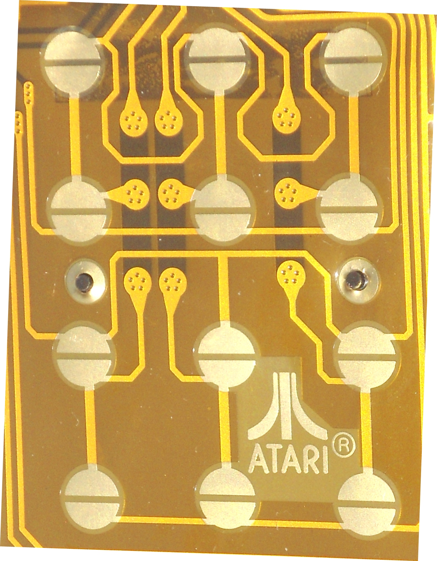
One of the very obvious upgrades that can been very easily seen, is Best changed the 30 year old interlocking E grid contacts (19 positions) into the State of the Art back to back D Gold plated contacts with larger contact (switch closure surfaces) surfaces. In case of the 4 CX52 fire button contact pads, Best specified the back to back D contacts, be stretched out to an oval shape contact pads, to be fully / backward compatiable with all versions of the older Atari CX52 carbon dot pads. This is the same Start of the Art back to back Gold plated D contacts Best used on the New Atari CX78 JoyPad rebuild kit Lifetime upgrade PCB boards. The larger back to back D contacts (back to back switch contact points) means the Best Rev. 10 flex circuit will have larger switch closure contact surface areas and will work with all of the many many different diameter carbon dots Atari used on the CX52 Joystick Fire Buttons, Auxiliary (START, PAUSE, RESET) pad and the numeric key pad over the years.
One of the unknown problems of the Atari CX52 flex circuits that 99% of the very very experienced Atari CX52 Joystick rebuilders and Atari CX52 Joystick users have not known about for the last 35+ years, is the 11 pin white pinch connector (where the Flex circuit contact fingers are inserted into) inside the CX52 Joystick top and bottom cases, does not insert enough pressure onto flex circuit 11 fingers. Best discovered this problem some 20+ years ago. When rebuilding Atari CX52 Carbon dot joysticks, we noticed that one completely dead (none of the carbon down pads / switches seemed to work) Atari CX52 Joystick, if we removed the internal flex circuit strip with 11 tin pated contacts / fingers from the CX52 internal cable pinch connector and reinserted back into the white pinch connector, all of sudden some of the non working old CX52 Joystick switch functions start to work fine again. Think of all of the thousands and thousands (for the last 35+ years) of completely dead carbon dot Atari CX52 Joysticks could of got a little more useful life out of them by simply reseating the old tin plated Rev. 9 flex circuits connector strip back into the white pinch connector.
This problem again came to Best attention again, when an old Best UK Atari customer contacted us about 5 years ago, saying 1 of his 2 All Gold CX52 Joystick he purchased from Best over 14+ years ago, just stop working completely. This was almost unheard of out of the thousands thousands of CX52 Joysticks we have sold all over the world for the last 16+ years. All we could think about, it is one or more of wires in the in the CX52 Joystick cable when bad or a female contact in the CX52 Joystick cable connector was damaged.
We asked our UK Atari customer to send it back into us, so we could take it apart and find out where the problem was. When our Atari Super Tech received the CX52 Gold Joystick back, the 1st thing he did is verify the problem on an Atari Factory Spec. Atari 5200 motherboard, to rule out the problem that was caused by the UK customers 5200 motherboard going bad. So he dissembled the returned CX52 Joystick and the 1st thing he did, is to remove Gold plated flex circuit from the C52 Joystick internal white 11 pin pinch cable connector and then reinserted it back into the CX52 white internal cable pinch connector. To his surprise, that Best 14 year old all Gold CX52 Joystick started to fully function again. So we knew this was a problem with the stock made Atari Rev. 9 Flex circuits and could be corrected in the future.
Mid March 2021 Best got in an E-Mail from one of our old Atari 5200 Customers. He said he bought the Best all Gold CX52 replacement upgrade Joystick parts from Best 2 to 3+ years ago and rebuilt both of his old carbon dot Atari CX52 Joysticks himself. The upgraded Atari CX52 Gold joysticks have been working flawlessly since then. But the last time he went to use them, both upgraded CX52 Gold Joysticks just stopped working completely. He said he traced the problem down to the Gold Rev. 9 flex circuits. He contacted Best because he wanted to buy 2 more Gold plated Rev. 9 Flex circuits to fix this problem. We asked him to 1st remove and reseat both Best Gold plated Rev. 9 flex circuits back into the white CX52 cable pinch connector 3 to 5 times. To his surprise, he E-Mailed back and said both Best CX52 Gold upgraded joysticks started to fully work again.
We asked our manufacture to increase the length of the 11 fingers / traces that fit into CX52 cable white pinch connector (see comparison picture about 5/8 way down this page). Best has noticed that some of the different white Pinch connectors (used by the 4 to 5 different cable manufactures that made the CX52 Joystick cables for Atari over the years) varied to some degree and the different Rev. flex circuits 11 fingers would not fully seat into bottom of the different pinch connectors used over the years.
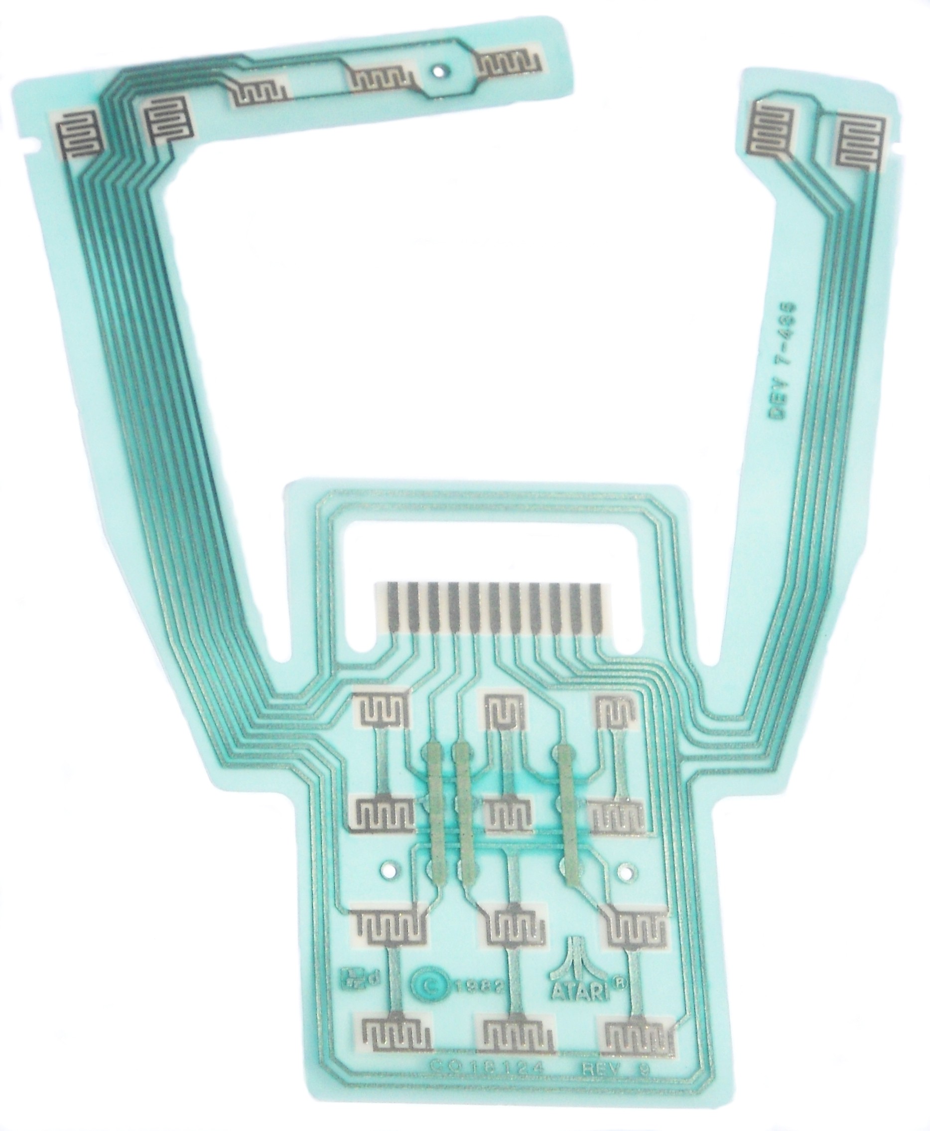
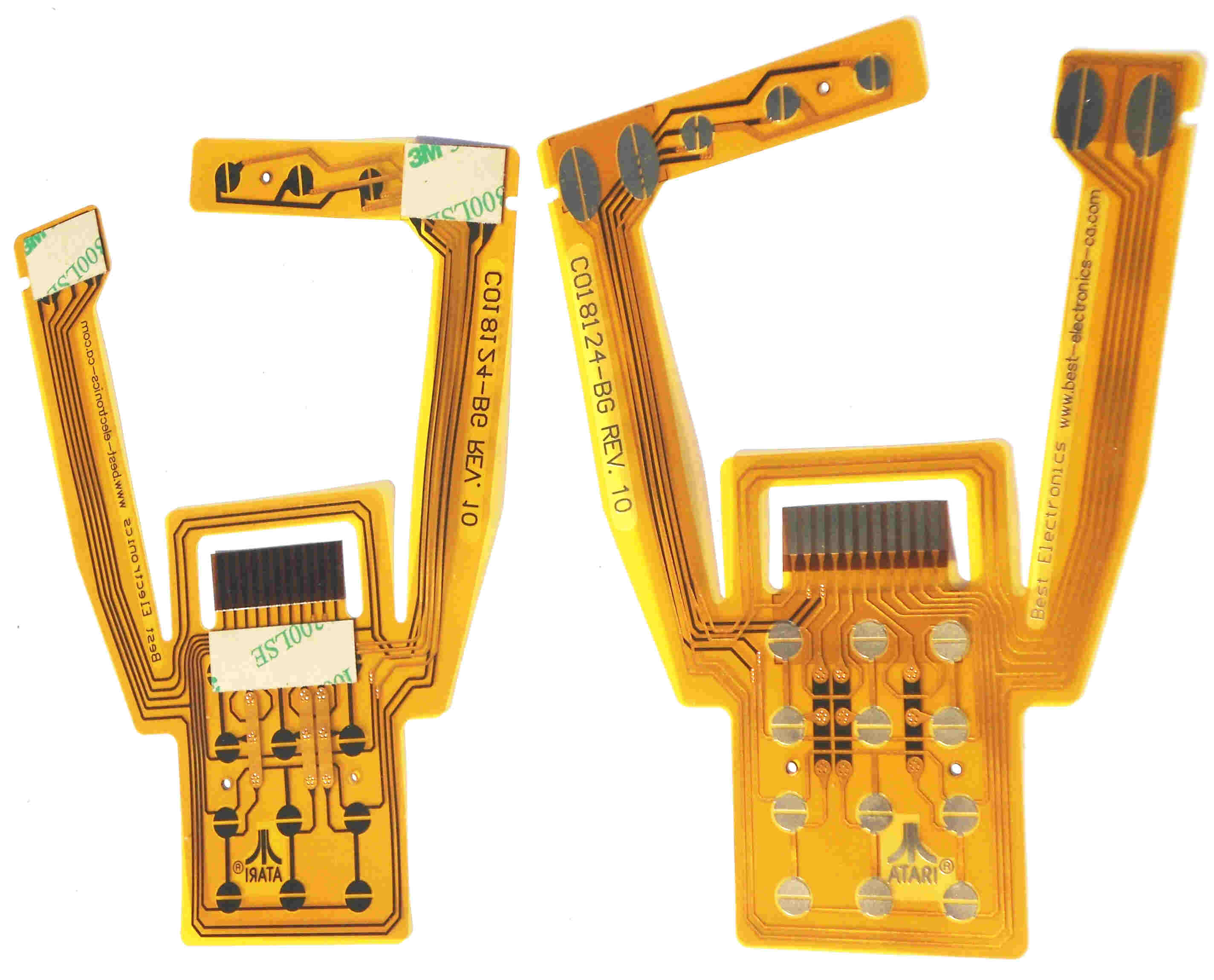
Best 1st article Rev. 10 Flex Gold flex circuit next to stock Atari Rev. 9 Flex circuit.
Another upgrade / change was to get rid of the 3 conductive Silver Silk Screened on Jumper bars on the top side of the different CX52 Flex circuits that were used to cross over (but not make electrical contact) certain metal traces and connector other traces on the top side of the flex circuits. This was an industry standard jumper method used on brand new state of the art 1st Gen. Flex circuits made 30+ years ago. These silk screened on 3 conductive silver traces jumpers / bars with enough age and pushing / flexing on the top of the CX52 Joystick numeric keypad for years and years, the 3 Silver traces became brittle and would crack. When this happened, whole sections / functions of the Atari CX52 Carbon dot Joysticks would simply stop to work. Best upgraded the New Rev. 10 Flex Circuits to the current Flex circuit technology of three solid Copper bars on the back side of the flex circuit with plated thru copper connecting holes to the top side of the flex circuits. This is the same type metal plated thru hole technology, that has been used on double sided printed circuit boards for the 20+ years. This type standard flex circuit PCB board plated thru hole circuit technology was simply not developed / used on 1982 vintage flex circuit designs of that era. When our manufacture FPC Engineering group made this circuit design change to the Rev. 10 version, they just copied the widths of the old Rev. 9 flex circuits Silk screened on silver conductive widths. Since these silk screened on traces were one of the failure rates on all of the different Rev. levels of the CX52 flex circuits Atari made over the years. Over all of the different Rev. levels (Rev. 1 to 9) of the flex circuits made, those 3 silk screened trace widths averaged around 1.60 to 1.75 mm. Best asked that the width of the 3 backside Gold plated metal bars / traces be widened to almost double the width, 3.26 mm. Instead of single plated thru hole (front to backside) our FPC manufacture went with 5 small plated thru holes (15 total per copper bar) per each of the 3 top side of the FPC connecting traces, to prevent any kind of plated thru hole circuit failures over the life of the flex circuit usage.
Best specified on the new Rev. 10 Flex circuits, that 3 new clear industrial strength, double sided adhesive tape strips be applied to the back of each left and right fire button arms and the third adhesive strip applied to the back side of the flex circuit around the top edge near the 11 connecting traces / top of the flex circuit support plate. This 3rd adhesive strip was applied by Atari to keep the 11 connecting traces on the flex circuit connecting strip from pulling out / riding up of the pinch connector during CX52 Joystick controller use. Anybody who has rebuild any quantities of Atari CX52 Joysticks, have seen many Atari CX52 Joysticks with these old double side tape strips on the inside of the CX52 Joystick. But after 30+ years after they were 1st installed, the old adhesive strips have lost their adhesive properties. So Atari Joystick rebuilders would use rubber cement or contact adhesive to hold a new Rev. 9 Atari flex circuit in place during reassembly of rebuilt CX52 Joystick.
Rev. level on this New flex circuit to be changed form 9 to Rev. 10
Atari Part number to be changed from CO18124 to CO18124-BG.
Best Electronics name and web site address to be etched on the new flex circuit arms.
Hard Gold plating thickness was increased to between 40 to 50 Micro inch range which Best had to pay extra for. Hard Gold plating per US Mil spec: MIL-G-45204 TYPE 1. The old Best Rev. 9 flex circuit Gold plating thickness averaged between 10 to 11 Micro inch Gold plating thickness.
Best CX52 Rev. 10 Upgraded / Enhanced Gold Flex Circuit CO18124-BG $20.95 Min. Sale 2
See 3/4 way down this page to see the new Best recommended Rev. 10 Flex circuit installation steps.
History
In 2005 Best contacted over 25 to 30+ local Plating companies in Silicon Valley and up towards San Francisco. Of course all were plating components / printed Circuit boards for hundreds and hundreds of high tech Silicon Valley companies and getting Top Dollar for their services and working 3 shifts. A lot of the local plating companies said they were not interested in doing small lots (75 to 100+ Qtys) of Gold plating on the new / old Atari CX52 Joystick flex circuits. A few of them ran some sample tests on Gold plating the flex circuits. Either they over etched / destroyed / damaged the flex circuit 3 silver trace jumpers (when this happened, certain sections of the CX52 Joystick numeric key pad functions would not work at all), over acid etched (a process to prepare the CX52 circuit metal traces for plating) the flex circuit metal traces or in one over etched case, the very stiff Gold plated circuit samples made a cracking sound when flexed. One platter managed to successfully Gold plate the CX52 flex circuits, but their cost quoted to plate them was about 3 times the cost other platters had quoted Best. After months of months of searching Best found only 1 local plating vendor who could plate the old new Atari CX52 at a reasonable price.
To keep costs on each Gold plated CX52 flex circuit to an absolute minimum cost, Best arranged to do all of the prep work (normally done by the plating vendor setup people at an extra prep cost) on the flex circuits before they were sent to the vendor. This entailed burnishing all of the 30+ year old tin plated metal surfaces to expose fresh metal surfaces. Next cleaning them with a chlorinated solvent to remove any removed tin metal, clean off any old oils and clean off any 30 year out gassed coating from the old silk screened on Green flex circuit coating. Back 30+ years ago, the flex circuit protective coverings were silk screened on and let to air dry. That means the protective silk screen coating could out gas for years and coat anything in the general area round the installed flex circuit. A prime Atari example of this 30 year old silk screen protective coatings out gassing problem, is the well known out gassing / coating problem on the Atari 1200XL internal white Mitsumi keyboard mylars that caused all of the Atari 1200XL keyboards to near 100% fail over the last 35+ years. The New Best Upgraded / Enhanced 1200XL Keyboard Mylars and the Best Rev. 10 CX52 Flex circuits use a State of the Art silk screened on coating, that is UV light cured. Once UV cured there is no out gassing of the silk screened on coatings at all.
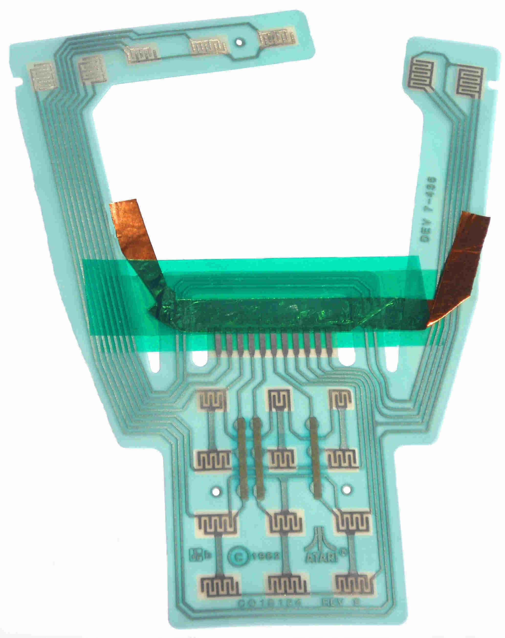
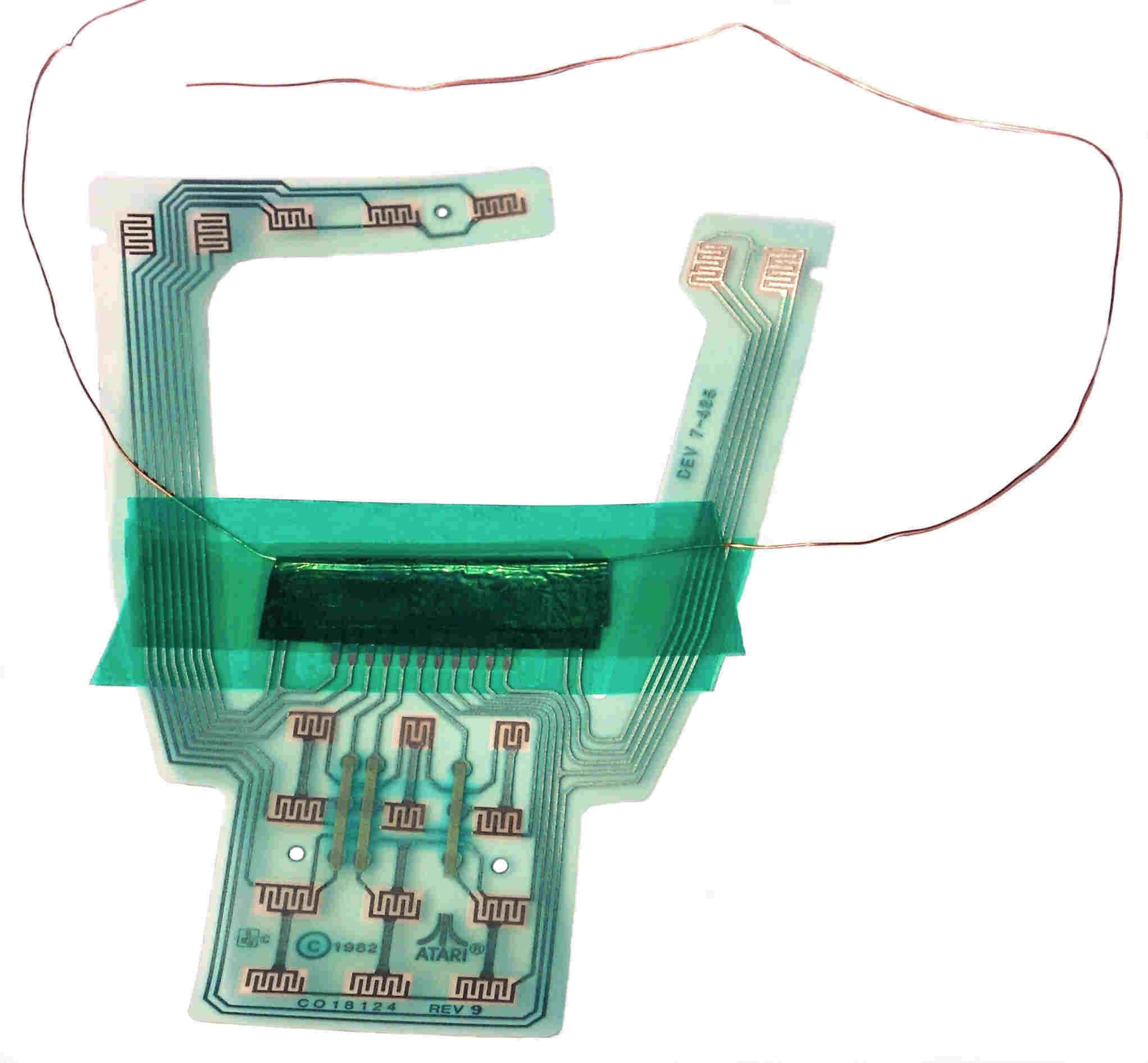
Then each flex circuit was hand taped up by Best with green acid resistance tape (2 strips) and a thin copper foil strip (makes electrical contact with the 11 metal connector fingers on the middle of the Rev. 9 Flex circuit) required for the electro / chemical plating process.
For the last 16+ years, to save costs on each Gold Plated Rev. 9 flex circuit, Best did the hand prep / set up (normally done by the platter set up people at an extra cost) on the thousands and thousands of 5200 Gold flex circuits.
Before Best Electronics was started, Brad the owner of Best Electronics worked in Silicon Valley at a few different companies, including a Mil Spec company that supplied many different components to the Military and Aero Space Industries. A few as a process Engineer and a few working with and running two different Q.C. departments. So he was use to dealing with a lot of different component supply vendors / plating companies / heat treating companies and many different metal processing companies and what can go wrong with them.
One of the very last Rev. 9 Flex circuits Gold Plated by Best Electronics. It was hand prepped for electro Gold plating process using the Copper tape and 24 gauge wire method. Notice the non Gold platted exposed tin fingers area where the applied Copper foil tape strip (to complete the Electrical circuit) made contact the flex circuit 11 metal fingers / traces during the electro chemical Gold platting process. When this hand prep method of plating was 1st used (15+ years ago), we could get very good Gold plating on the CX52 Flex circuits with only about 1/16 inch wide of non plated / copper tape contact area. The last Rev. 9 Flex circuit above required close to a 1/4 inch of copper tape contact to get the same high quality of Gold Plating. Remember this non Gold plated 11 finger area is where the Atari CX52 cable white pinch connector metal contacts made contact with the flex circuit This non Gold plated area on the 11 contact fingers was Corrected / Upgraded / fully plated on the new 2021 Best designed Rev. 10 Gold CX52 Flex circuit.
The plating process involves a lot years of experience and a lot of trial and error tests on any new samples / metal parts by the plating process Engineers / Companies. They have to control (with a lot of State of the Art process control equipment) all of the different processing settings like bath temperatures, length of time in the large plating tanks, electrical platting settings, chemicals types / mixes, chemical concentrations and when to add more chemicals or completely change out / drain the old / used up chemicals out of a used large plating tank batch. Even the last metal product to be plated (what it takes out of the plating bath chemicals and what the electro plating removes off that same metal product and leaves slight metal residue in the plating bath mixture) that was Gold plated in the same tank. These can all effect the Gold plating quality you will get on the next (like the Atari CX52 flex circuit) product to be plated in the same bath. You can have a proven plating process that has been working well on a component for 10+ years without a single problem (because of the exact plating process its well documented in the by the production department set up people) and them all of sudden have one bad lot or other lots / runs have a problem(s) in a row. Which causes the Gold plated parts to be rejected. In a lot of cases the bad or poor quality Gold plating can be removed from a standard metal parts and re-plated again, but in the case of the Atari CX52 flex circuits, a lot of times the second acid bath to remove the bad Gold plating quality, would over etch the flex circuits and damage the 3 Silver silkscreened jumper traces (in the middle of the Rev. 9 Flex circuit) and cause the whole lot of flex circuits to be scraped out. So over last 15+ year Best has had to scrap out hundreds and hundreds of Atari CX52 Flex circuits and write off the cost of the flex circuits themselves and the Best in house prep labor. To the average outsider, it seem like a lot of black magic is used in the electro plating process / industry.
Present day
Best has always had the same type of plating problems on the Gold plating on Atari CX52 flex circuits for the last 16+ years. 4 to 7+ lots not a single problem, than all of sudden problems like the Gold plating was flaking of the flex circuit traces, discoloring of the Gold plating appearance or completely missing Gold plating. After a year the one approved local Gold plating company, was giving Best a hard time with stretched out delivery times, prices increases and in the end flaking off the Gold plating again (one of the ways a plating vendor was telling you to go away and find another company to do your plating). In the end Best felt that the PCB Gold plating company with so busy (3 shifts) with Silicon Valley Gold PCB board plating, they did not want to do the small lot Gold plating of the Atari CX52 flex circuits for Best any more.
So the search for a new platter stated again. Luckily Best finally found another / single local plating vendor who could do small batches of the Atari flex circuits with quality Gold plating for the last 14+ years and took pride in producing the highest quality Gold plating they could. They were use to during Mil Spec (Military Specified quality standards) Gold parts. But with this new single source plating vendor there were still lots of Flex circuits that were destroyed or damaged and could not be salvaged. Again a total write off for Best.
Recently this old school Silicon Valley plating company changed hands / owners. It was like starting over with a brand new platter. Weeks of working with them to get the Atari CX52 flex Gold plating process back to the old standard. Four to Five plating lots latter, we where still having minor Gold plating problem with the New / Old plating company.
About a year before our present Gold Platter changed hands / sold to a new owner, they changed the Rev. 9 Flex circuit platting prep method. They doubled the width of the thin copper stripe (under the two pieces of green acid resistance green tape) and added a piece of 24 gauge copper wire. This was done to get more electrical current to the flex circuit metal surfaces during the plating process, to get a better Gold plated finish. One of the draw backs of this new Gold platting set up process, it required more (about 80%) of the 11 metal fingers on the flex circuits be covered by the thin copper strip, which means less Gold platting on the contact fingers / traces.
The Project begins
To get rid of this bottleneck CX52 Joystick Gold upgrade part and to finally stabilize all of the costs for it (the one and only CX52 Gold upgrade parts, Best had no cost control over for the last 16+ years), Best had to commit to the following:
1. Over a year of Best Engineering time into the CX52 Rev. 10 Gold flex circuit upgrade project.
2. Commit to another New fixed one time tooling $$$ cost, which had to be paid up front.
3. To meet Minimum production run / 1st order requirements, Best had to place a 1st order for the New Upgraded / Enhanced Rev. 10 Best CX52 Gold Flex circuits equivalent to a 12 to 15+ year supply of the old Rev. 9 flex circuits normal usage. Again which had to be paid up front.
Best sent some of the Atari CX52 New tin plated flex circuits to our over seas vendor and asked them if they could find a vendor to Gold plate them for Best on March 09, 2020.
After they received the Atari tin plated CX52 Flex circuits, they sent the word back to Best, that the Atari 30+ year old flex circuit design / base materials was not compatible with current high temperature / high speed Gold plating process and would be damaged or destroyed in the current Gold plating processes they used. There only suggestion was to make a new State of the Art CX52 flex circuit they could produce for Best. At 1st Best resisted this suggestion because we still had about 5,000+ new / old Atari Rev. 9 flex circuits left in stock.
But after we really thought about it for a while, Best has always known there been design problems with the Old Rev. 9 Atari flex circuit design (that was one of the many many extra reasons why the old Atari Carbon dot CX52 Joysticks always failed early) that could be Corrected, Upgraded and Enhanced to another Best State of the Art Lifetime fully Gold plated Atari replacement part. The final cost per flex circuit would be fixed for the next 12 to 14+ years. So Best asked our vendor to give us a rough cost for tooling costs / quotes and min. lot qtys per order. The early figures they gave use were within reason. So on May 12, 2020, Best sent ($$ shipping cost) samples of complete Atari CX52 Joysticks, CX52 cables, every different carbon dot (from small to very large carbon dot) silicon pads used / made by Atari for the last 20+ years and the latest Best Gold dot pads to our manufacture. Complete Engineering Specifications for the new Best Lifetime Gold CX52 flex circuits was included with the sample shipment.
On May 24, 2020 our manufacture said they received the CX52 Joysticks and all of the different carbon dot and Best Gold dot CX52 silicon pads. They said their Engineers would review Best Engineering upgraded document and get back to us. Also the world wide COVAD 19 virus, put a major delay in the Best Rev. 10 new flex circuit project.
On September 4, 2020 we got in an E-Mail from our over seas 20+ year manufacture we have been working with. Their Engineering department finally got the free time to start to work on the Best Upgraded / Enhanced CX52 Joystick Gold flex Circuit design / project. Although Best sent a complete set of Engineering specs on the new Best CX52 flex circuit, they still came back with 8 questions on the Engineering specifications we sent them. All questions were answered and Best waited for their Engineering feed back on all of our answers to them.
On September 19, 2020 we got an E-Mail from our manufacture with some new Best Rev. 10 Flex circuit information upgrades we requested.
1. They confirmed that they could do the 4X thicker (40 to 50 Micro inch range, per US Mil spec: MIL-G-45204 TYPE 1 Best requested, compared to the 10 to 11 Micro inch thickness Gold finish) our present Gold platter was applying to stock made Atari Rev. 9 Flex Circuits over the last 15+ years. Of course this upgraded feature would cost more per finished Rev. 10 Best flex circuit. This means in theory after 10 to 15+ years continues 5200 Gold Joystick use, it might be possible to wear off some of the 11 micro inch thick Gold platting on the Best Rev. 9 flex circuits. So the 4X thicker Gold plating should last you 4X times more of continues use with the Rev. 10 Best Gold flex circuits
2. Their FPC (Flexible Printed Circuit) Engineering group give Best a choice of the Color of the coatings they would use to cover the exposed circuit traces, like the light green color the last FPC manufacture used on the last group of Atari 5200 Rev. 9 Flex circuits made. By the way, over the last 20+ years Best has been rebuilding CX52 Joysticks, the different stock Rev’s / FPC manufactures Atari used, the flex circuits colors have ranged 3 to 4 shades of the Green, White and a very Dark Blue flex circuit coatings with Tin plated metal exposed circuits and even some even conductive carbon black silk screened on traces. They said they could give Best just about any FPC color coating we requested, but the highest quality (and more expensive cost) they had and recommend Best use was Gold color coating. So we give them the go head to use the higher quality FPC Gold coating.
3. They confirmed the final cost ($$$) of the Test tooling to 100% test all new Best Rev. 10 Upgraded 5200 flex circuits made. Payment for test tooling to be sent in the future, after the 1st article samples are approved by Best.
So Best waited the conformation on the balance of upgrades we requested on the new Rev. 10 flex circuits.
On September 20, 2020 received an E-Mail from our manufacture asking how many prototype new samples of the Rev. 10 Gold flex circuits we required for our CX52 Joystick tests.
On October 18, 2000 Best got an E-Mail in from our manufacture saying they had a initial cost to design, produce and ship10 Best Rev. 10 CX52 new Flex circuit samples to Best. So we sent them $$$ the same day.
On October 24, 2000 Best received a full set of set 6 Rev. 10 Flex circuit Engineering prints, see one example below. After a quick review of them, most of the requested changes / upgrades Best asked for were done. But a few were not done. Best requested that the 4 Fire button round Gold plated pads, were to be changed from round back to back D pads to oval shaped pads. This was done so the Best Rev. 10 Flex circuits would be backward compatible with the Atari made triple dot (top and bottoms sets) of carbon dot pads (which had a wider width between the 3 carbon dot pads). With a standard split round Gold pad, only about 1 ½ of the round carbon dot pads out of 3 carbon dots would come in contact with mating flex circuit round Gold plated pad. See triple dot / flex side by sides pictures below.
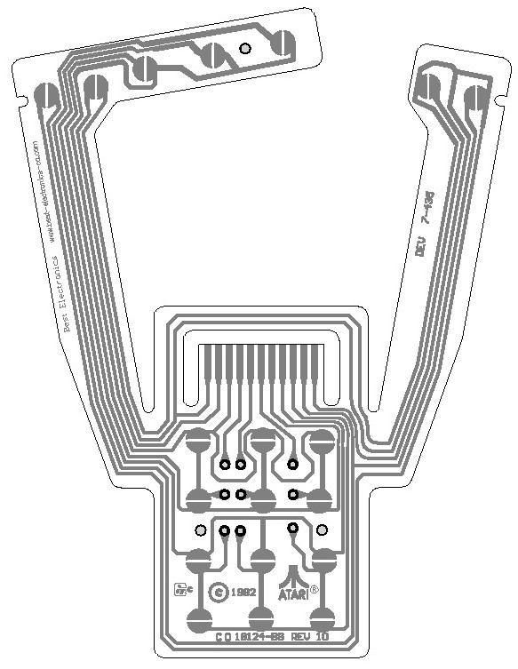
1st Rev. Print of the New Best Rev. 10 Upgraded / Enhanced Gold CX52 Joystick Flex circuit.

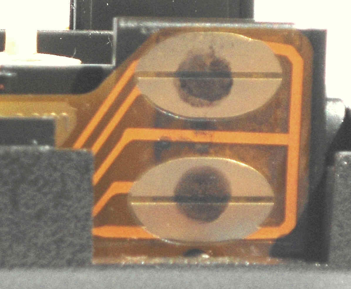
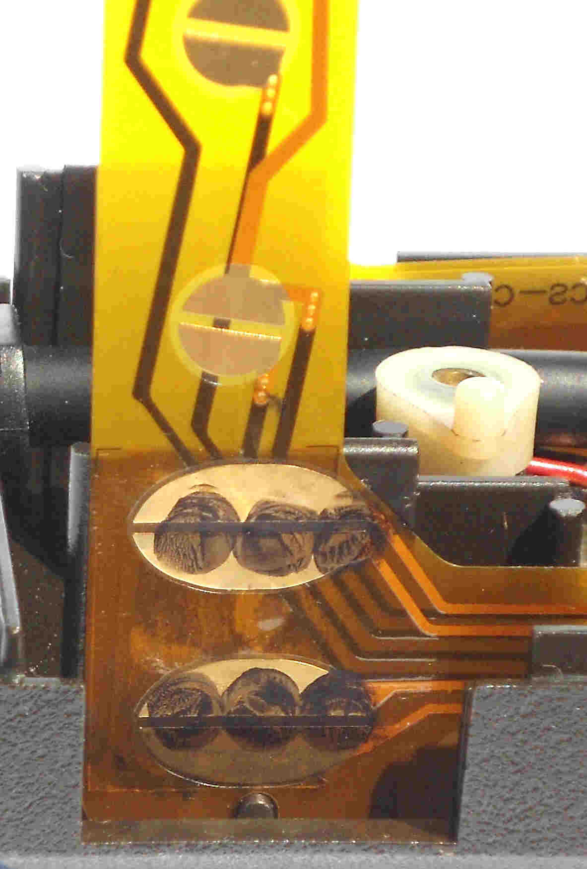
Right: Blown up view (of the above print) of the left side fire button flex circuit. Left: triple carbon dot fire button next to the of close up view of the flex circuit fire button area as Installed into the CX52 bottom plastic case. Best spotted that the split angle between the back to back “D” Fire button Gold contacts pads was angled up and would not make proper / full contact with the old Atari fire button with the 3 in line carbon dots, when the fire button was press down onto the flex circuit. Also the back to back D shaped fire button Gold contacts were undersized.
On November 17, 2020 we got in an E-Mail in from our manufacture saying they still did not understand one of the requested changes to the Best new Rev. 10 Gold Flex Circuit. It was regarding the left and right top and bottom flex circuit 4 D shaped fire button contacts. To clarify this point, Best drifted up a quick Engineering print showing the new flex circuit installed in the CX52 Joystick bottom plastic case. 1st side view of the CX52 Joystick bottom case showed
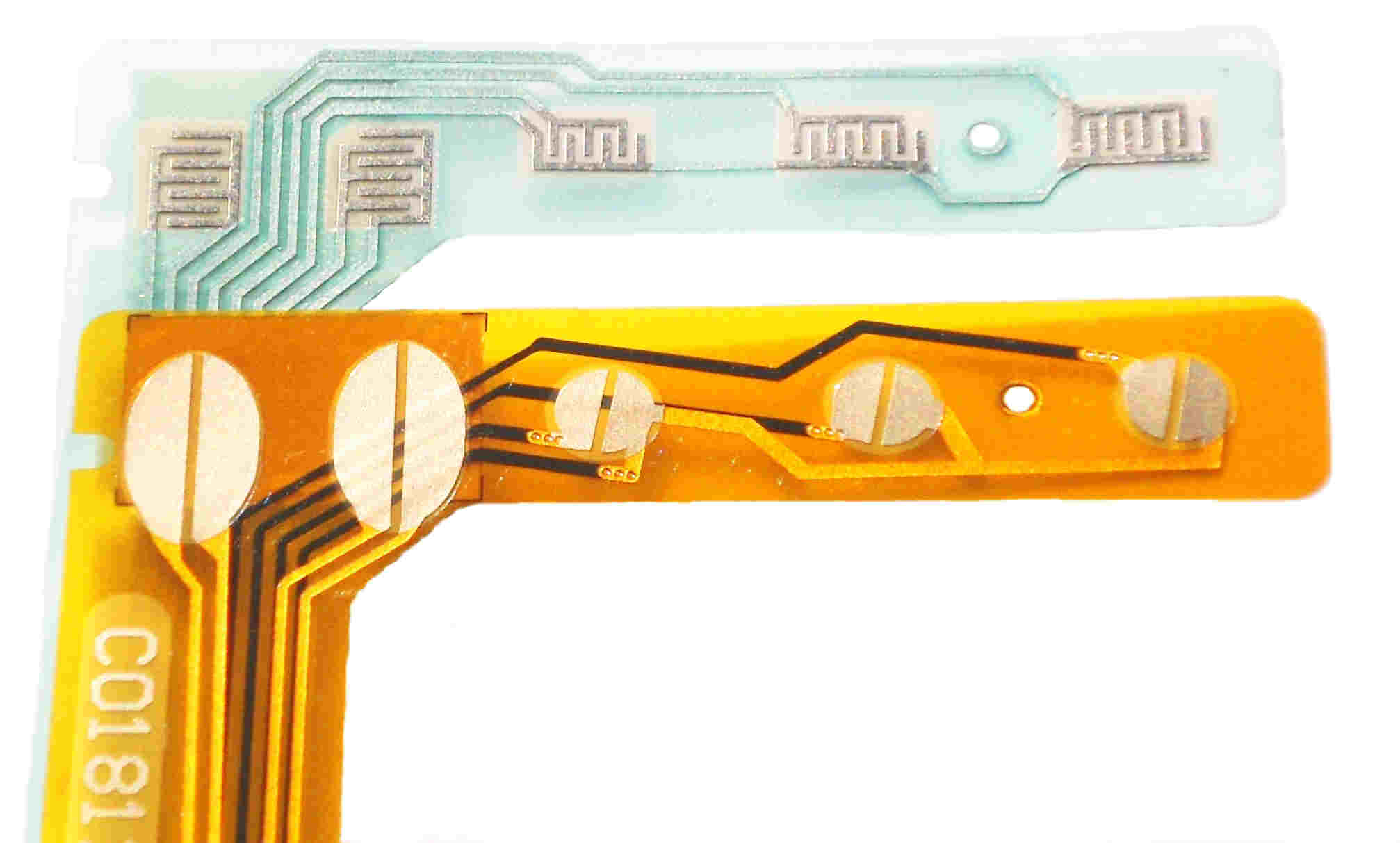
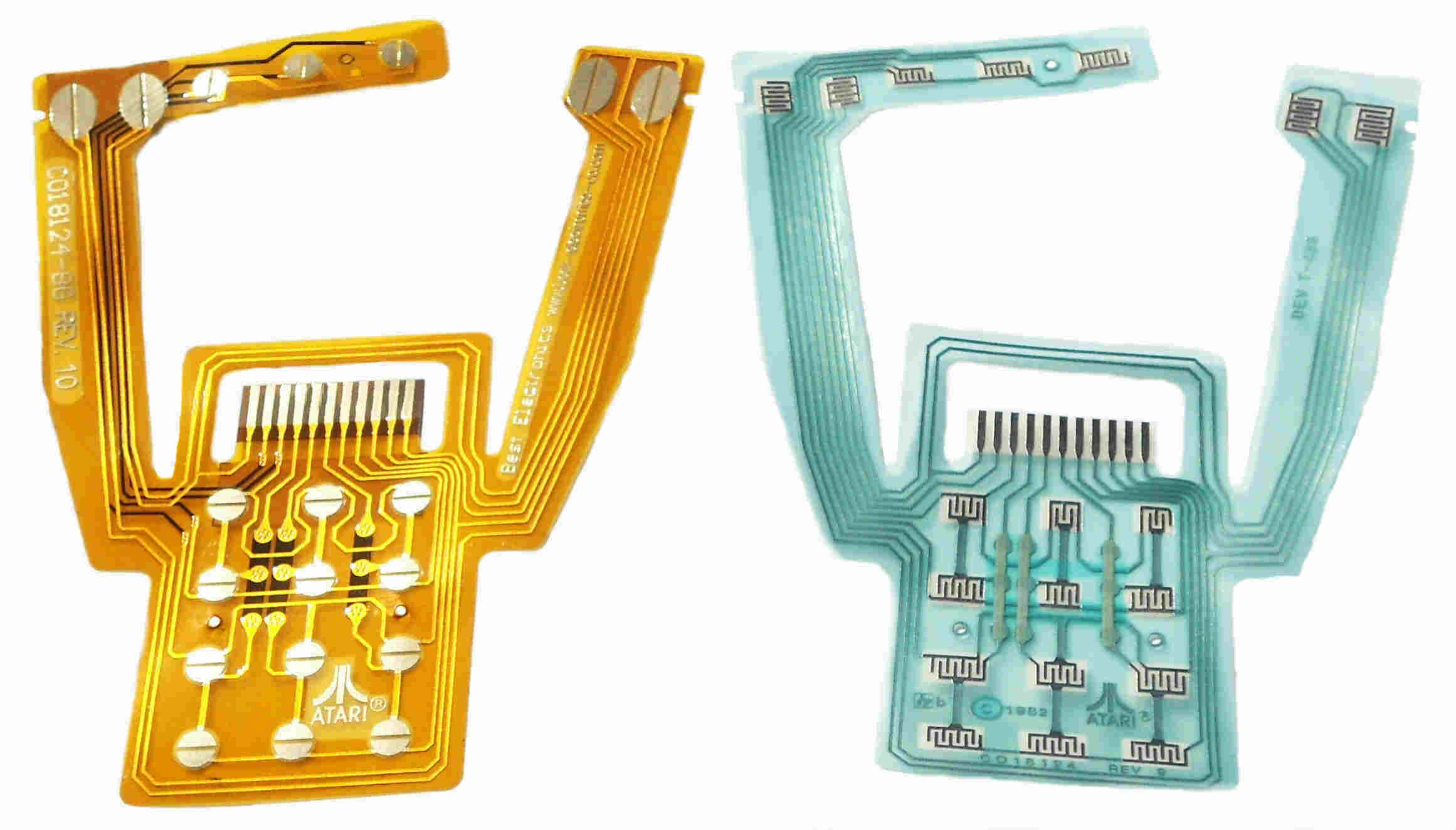
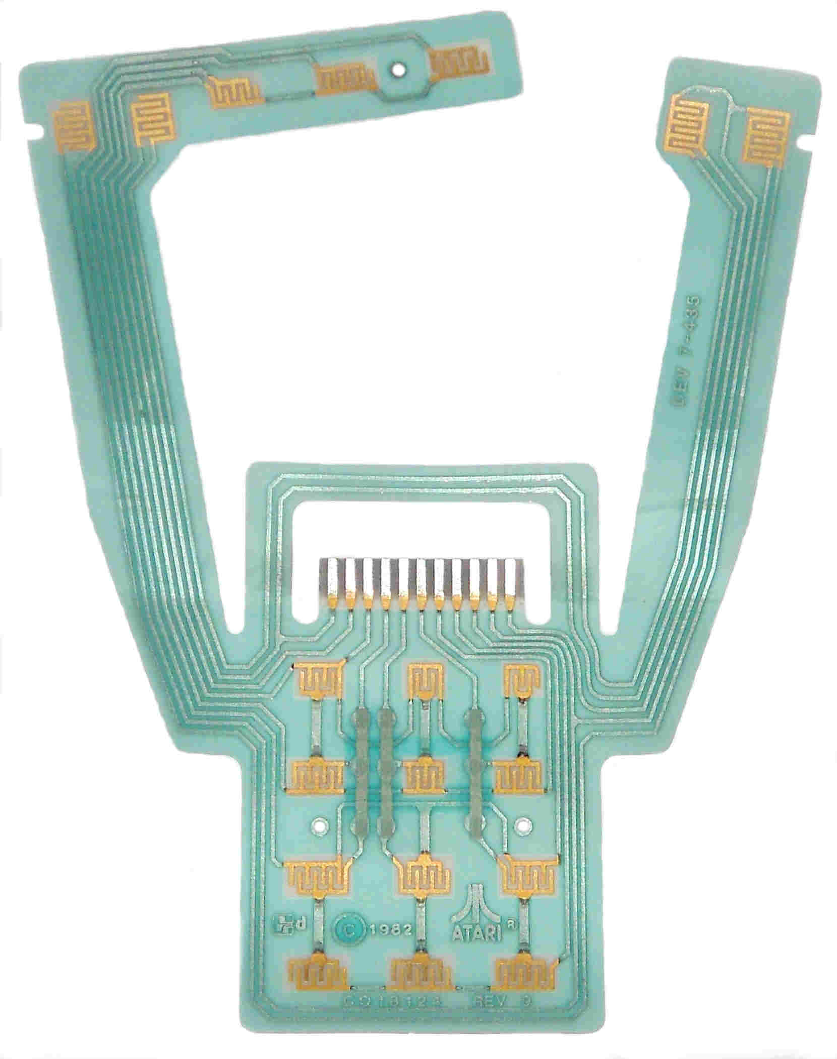
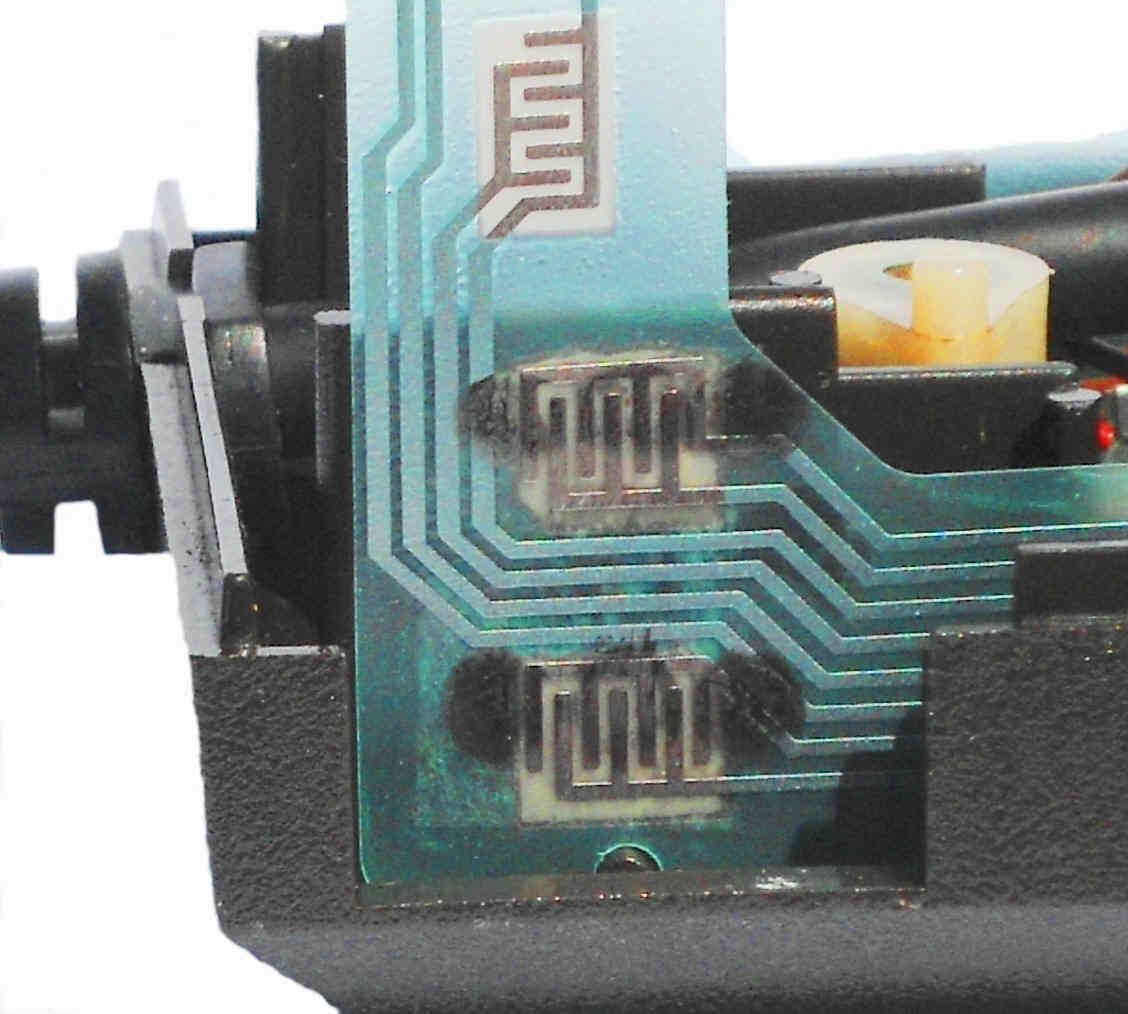
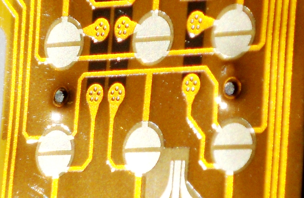
Direct comparison of the Atari stock Rev. 9 flex circuit tin plated E interlocking contact grids to the Best Rev. 10 all Gold plated Contact disks
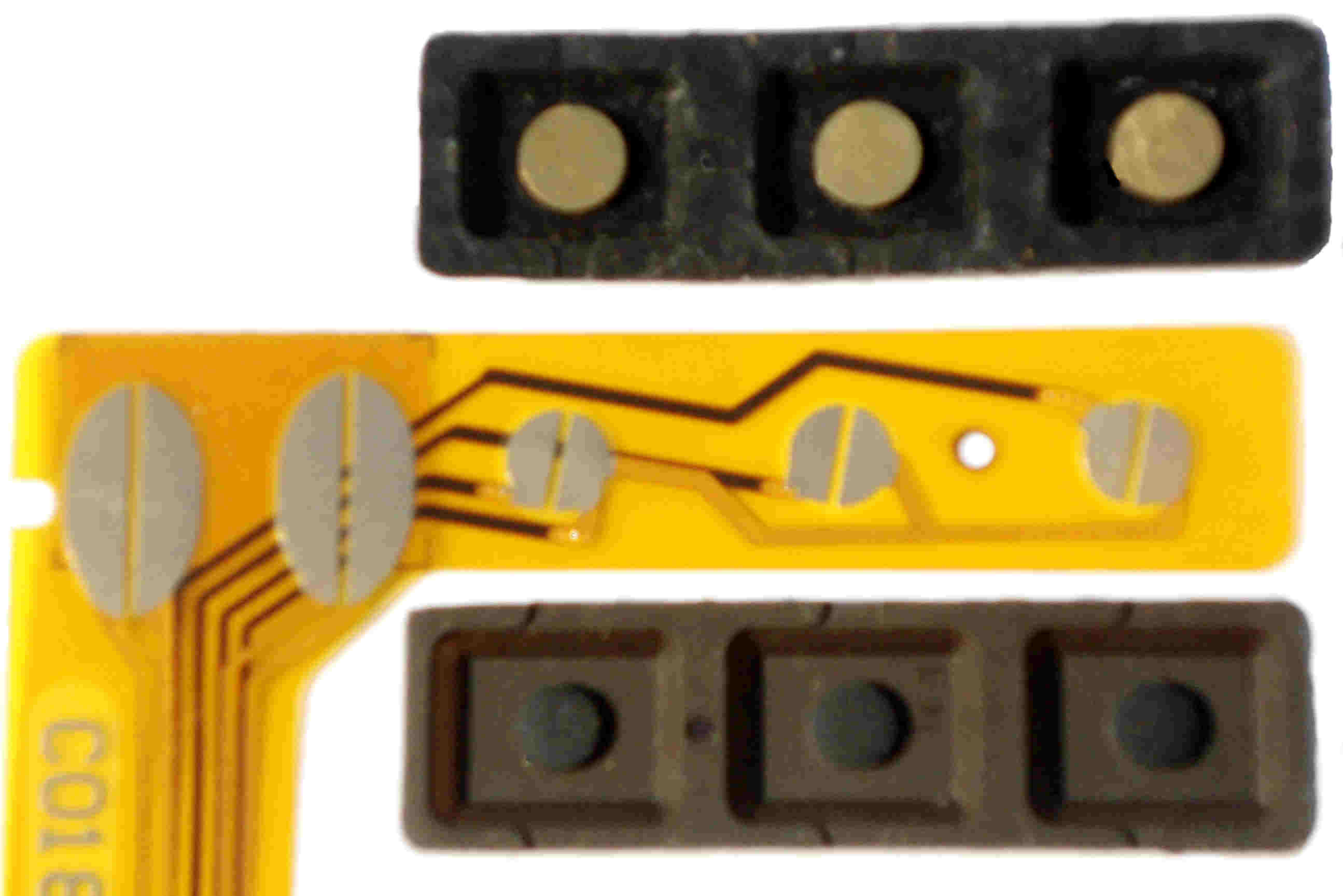
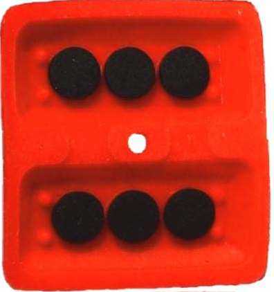
Best Gold plated Auxiliary keypad (top) and below one of the many different Atari made Carbon dot (with different diameter carbon dot sizes used over the years) Auxiliary keypads made.
how round top to bottom D contact pads, as currently designed, the split between them angled up about 20 degree angle and how it would not make full contact the old Atari small triple carbon dot conductive pads (see black ink fire button transfer tests on old Rev. 9 and Best Rev. 10 flex circuits below). The second side view showed how if the split between the top to bottom D contacts were parallel to the bottom of the CX52 case, it would make more (but not complete) contact with the triple dot old fire buttons. The third side view showed if the top to bottom D shaped (round) contact pads were changed to a oval shaped D pads with the split between the pads, it would now make full contact with the old Atari triple dot fire button carbon dot conductive 6 pads.
Several E-Mails and sent prints back and forth, on November 23, 2020 Best received an updated / 2nd Rev. print set on the Best Rev. 10 Gold Flex Circuit. Again Best spotted some features that were still not on the 2nd full set of Rev. 10 flex circuit prints. The same day Best sent back a correct version of one of the prints with full requested details changes again. On November 25, 2020 Best received a 3rd set of Flex circuits prints. The same day Best again sent back another corrected print with full requests changes.
.jpg)
One of the 2nd set of prints with some of the requested changes done. Note the corrected fire button back to back “D” contact split angle. Also after several different requests our Manufacture finally changed the Gold plated “D" shaped fire button contacts to the requested Oval shaped fire button contacts to fit (backwards compatiable with all of the different version carbon dot fire buttons ever made) the Atari older 6 dot (triple top and triple bottom) carbon fire buttons.
On December 2, 2020 Best received a 4th set of corrected Rev. 10 Flex circuit prints. All of the requested changes were done. The only minor problem was some ID Text information still needed to be changed / corrected.
On December 3, 2029 Best received the 5th and final set of Rev. 10 Flex circuit prints. All changes we done and approved. We told our PCB manufacture to preceded to produce the 1st article samples of the Best New Rev. 10 CX52 Joystick Gold upgrade flex circuits.
On December 7, 2020 Best received an E-Mail from our manufacture saying it would take up to 10+ days before they could produce the 1st article samples of the Best Rev. 10 new Gold Flex circuits.
After several weeks of back and forth of pictures sent and received of the 1st article samples of the new Best Rev. 10 Upgraded / Enhanced CX52 Gold Flex circuits, we approved them. So on January 05, 2021 our Manufacture said they set Best 10 pcs of the 1st Article Rev. 10 Gold Flex circuits for our long life cycle tests, dimensional checks and function and fit tests.
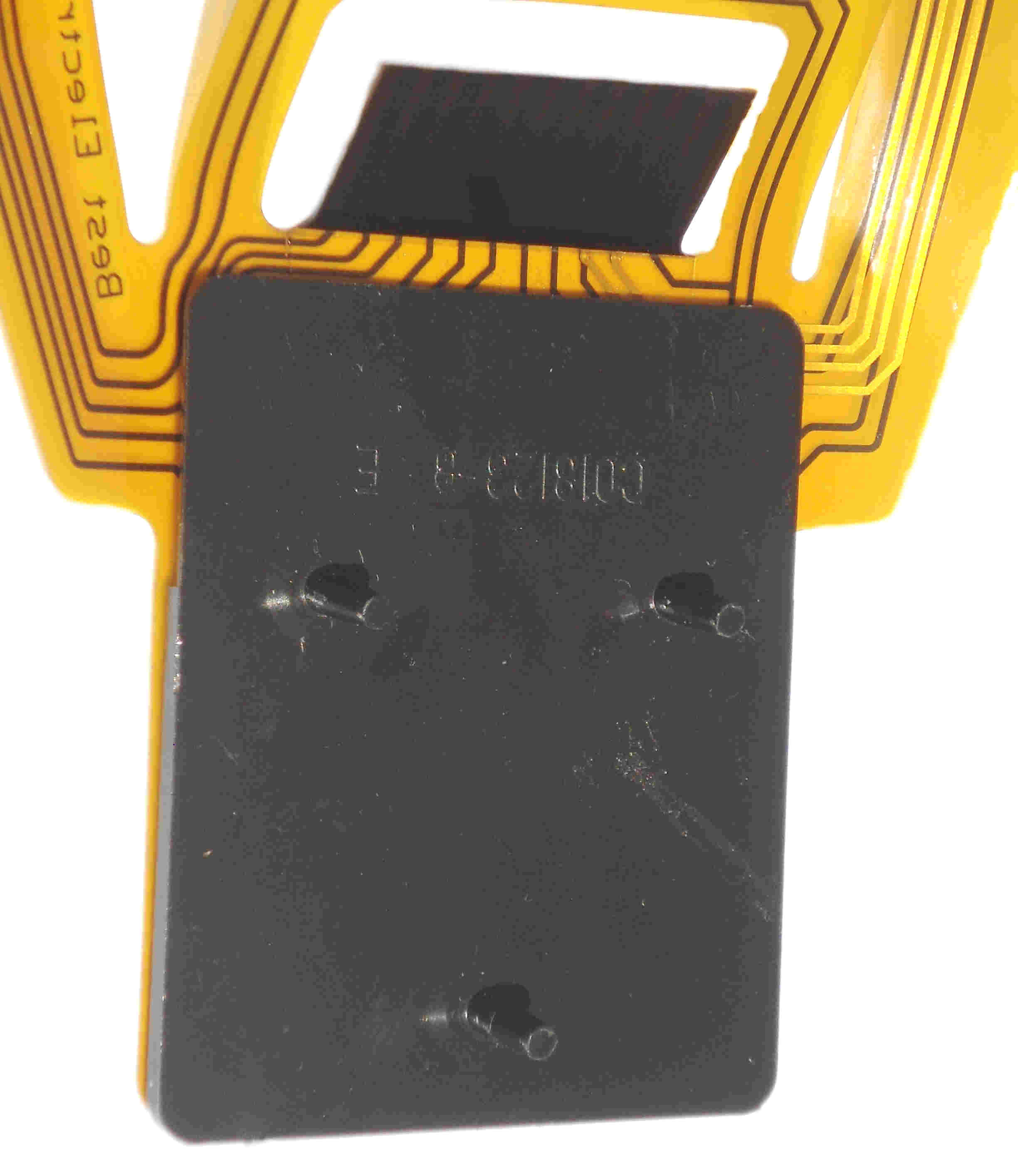
Back side Front side
1st Article of the New Best Rev. 10 Upgraded / Enhanced CX52 Joystick internal Gold Flex Circuit
On January 12, 2021 Best received the 1st article 10 samples. A couple of minor problems were spotted right off and couple of things that need to be corrected on the final Best Rev. 10 Gold CX52 Flex circuits. So for the next few weeks functional and continuous long life cycle tests we run on the 10 samples.
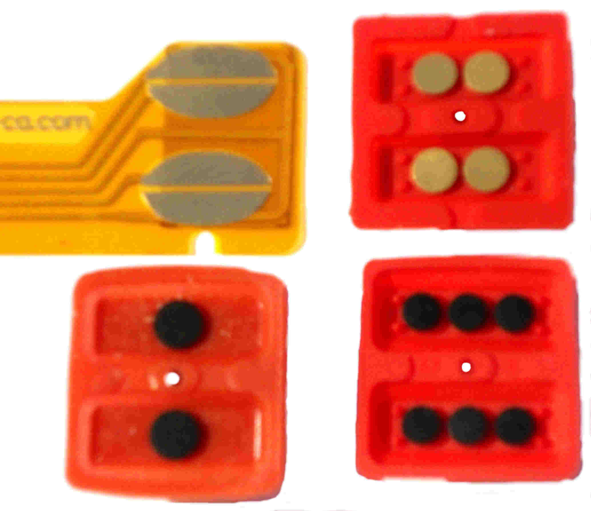
Direct comparison of Atari 5200 CX52 Joystick fire buttons to the new Best Rev. 10 upgraded Gold flex circuit right side fire button pads. (Top right, the Best 2nd Gen. new tactical feed back feature Gold plated Fire button. Below 2 of the many many different Atari made Carbon Dot fire buttons made over the years.
Best ran many different tests on the New Rev. 10 Flex circuits. One test run was a black Ink transfer Test. We inked up old single and triple dot old carbon fire buttons to verify where the carbon dot(s) would make contact with new Rev. 10 Flex circuits.
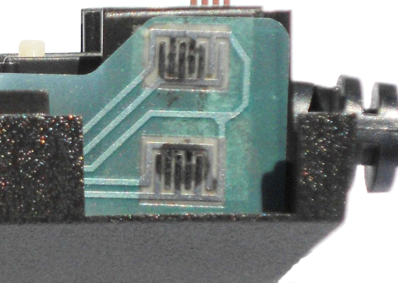
Same inked carbon dot fire button tests were run on the old stock Atari Rev. 9 Flex circuits. Left: Large single carbon dot fire button contact point is under sized compared to the mating E contact locking grids. Right: Triple carbon dot fire button is over sized and over shoots / does not full contact the Rev. 9 Flex mating E locking grid switch.
New features on the New Rev. 10 Flex circuits that Best was impressed with the 1st article samples:
1. The original Atari 1982 design single sided (similar to old / very early single sided (circuit board traces on one side) printed circuit boards)) flex circuits have been upgraded to newer doubled (circuit traces on the front and back sides of the flex circuit) sided circuit design.
2. The larger Oval / Larger shaped Gold fire button pads (4X) that are backward compatible with the older Atari 6 dot (3 top and 3 bottom fire button pads) and all of the different size (small to large single dot) carbon dot fire buttons Atari made over the years. In theory the over sized Gold fire button flex circuit fire button oval pads would extend the useable life of any triple carbon dot old fire buttons.
3. The New Best specified 3X wider width trace jumpers (on the backside of the flex circuit, vs the original Atari CX52 flex circuit that had the 3 skinny silver silkscreen jumper pads on the top side of the flex circuit. With enough use / time (numeric key pad buttons pushed down over and over) on the CX52 keypad, these skinny silver traces would start to crack and whole sections / functions of the CX52 Joystick would just stop to function / work. Each new Best wider jumper trace has multiple / extra copper plated thru holes (front to the backside of the flex circuit) for much much better circuit redundancy.

2nd article sample of the Best Rev. Gold Flex circuit with longer (top to bottom) back stiffener strip behind the 11 Gold plated fingers, removed the non used locating hole on the top auxiliary strip and 2 large Gold plated rings around the Flex circuit number key pad area locating holes.
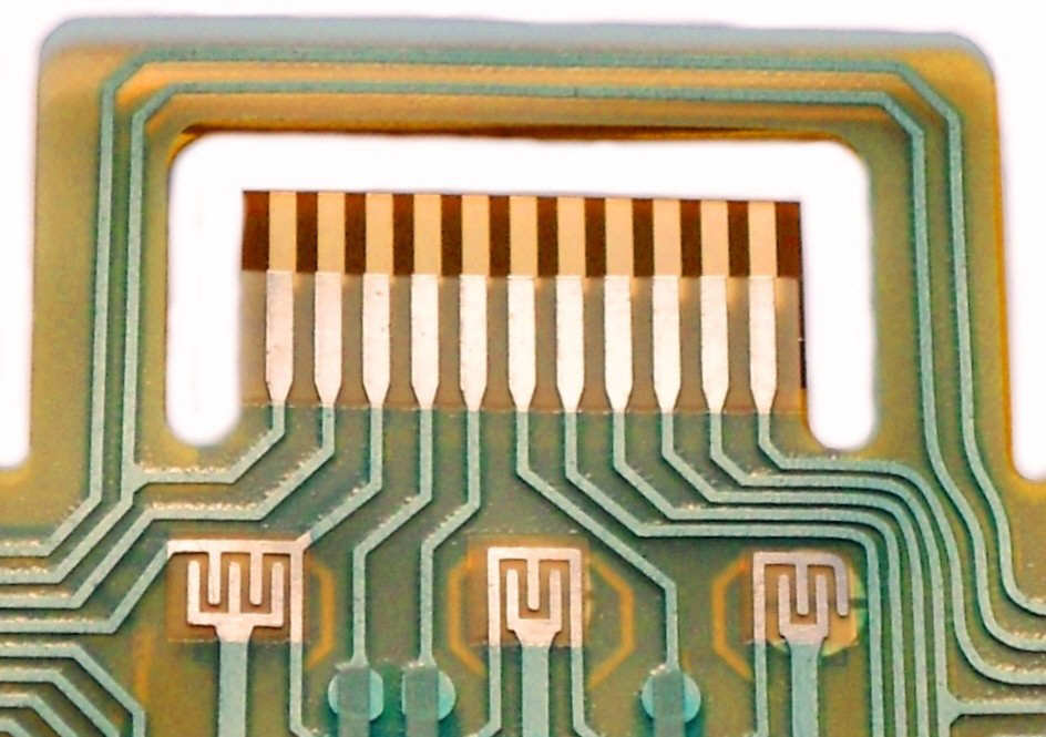
Old Atari Rev. 9 Flex Circuit laid over the new Best CX52 Rev. Gold flex circuit. You can see one of the upgrade features of the extended length of the 11 Gold contact fingers
4. One of the New features Best specified was the 11 fingers on the CX52 flex circuit connection to the CX52 cable pinch connector, was lengthen. Best has done this on just about every new Atari replacement mylar part we have every designed in the last 40+ years in the Atari Business. The main reason why we have done this, in the future if the end of the 11 connection metal traces ever got damaged, bent, folded over / dog eared corners or the Gold plating rubbed off from excessive insertion and extractions, you could always trim off a tiny piece of the longer flex circuit 11 fingers to get clean connection Gold traces again. In the case of the old CX52 Flex fingers Best felt that the Flex circuit connection fingers were not full bottoming out / making full contact with the different white CX52 cable internal metal pinch contacts / connectors used over the years.
5. The excellent very very high Quality of the State of the Art Flex circuit Gold plating technology was 200% better than we could ever expect with the older plating bath (hand prep) method Best has been using for the last 16+ years.
6. The New Best Rev. 10 flex circuit Polyimide base maternal is thinner (.10 mm thick) compared to the original thicker (.15 mm) feeling Atari flex 30+ year old Mylar maternal, it is a State of the Art Higher Quality Polyimide flex circuit maternal that is used in current Smart phones, Tablets, Laptops and all current Consumer based products that use internal Flex circuits.
Best did notice some problem areas on the New 1st article Rev.10 flex circuits that we asked our manufacture to correct.
![]()
2nd Article Rev. 10 Flex circuit as it goes into the white 11 pin female pinch connector. The stiffener tape behind the Gold fingers was lengthen upward, to make installing the Best Rev. 10 Gold Flex 11 pin connecting strip circuit into the CX52 white pinch connector a lot easier.
1. Because of the thinner State of the art flex circuit material, Bests installation tests found it was a little harder to push in the Rev. 10 flex circuit 11 Gold plated fingers / strip into the white cable pinch connector. The standard Atari CX52 flex circuit installation method for the last 30+ years, was to 1st install the old thicker Rev. 9 flex circuit on the CX52 support plate two raised location tits and then push the front edge of the 11 flex circuit finger into the white pinch connector. Although the Best Rev. 10 flex circuit reinforcing tape behind the flex circuit 11 fingers stiffened up that part of the flex circuit push in strip, the area above it (about 3/16 inch wide by 1 inch long strip) was still to flexible and would not allow you to put the proper pressure on the connecting push in strip to fully seat it into the bottom of the pinch connector in the bottom of the CX52 bottom case. The flex circuit connecting strip would flex / bend forward and back to much to freely (where is was not reinforced / stiffened) and would not allow you to easily insert the connecting flex circuit strip (with the 11 fingers on it) into white pinch connector, without a lot of extra installation effort, compared how easily the thick old Rev. 9 flex circuits connecting strip went / pushed into the white pinch connector. The only way you could get it fully seated in the white pinch connector, was to remove the CX52 flex circuit support plate and then push in the connecting strip into the pinch connector) and with 4 pinched fingers on both left and right sides of the flex circuit connecting strip push into the white pinch connector. Then add the support plate to the bottom side of the Rev. 10 flex circuit and seat the flex circuit support into the 3 support plate matting round support studs. Best felt if the stuffer tape strip height on the backside of the flex circuit fingers was extended up about a ¼ inch up, this would fix this insertion strip problem on the 1st article samples.
2. The stock Atari Rev. 9 flex circuit connecting strip (with the 11 fingers on it) is around .16 mm thick. The new Best 1st article Rev. 10 sample flex circuits with the stiffening tape behind the 11 fingers connecting strip measures .22 mm thick. Best felt this was still not enough of increase of the connecting strip thickness / pressure to fix / cure the known Atari stock flex circuit problem of losing connections with the metal fingers within the white pinch connector 5 to 20+ years down line. We asked our manufacture supply new flex circuit samples with a range of stiffening tape thickness, so Best could run insertion and extraction tests and find out which new thicker stiffening tape worked the best.
3. We noticed that there was a spacing problem on the New Rev. 10 flex circuit support plate spacing studs (the 2 extend up tits that the flex circuit mating holes fit onto). When the new 1st article Rev. 10 Flex circuits were installed on the flex circuit support plate, you could see cones / distortions / bubbling up in the flex circuit mating holes around the locating tits. Basically the Rev. 10 flex circuit would not set complete flat round the two locating tits. Best assumes this problem has been on all Atari CX52 flex circuit Revs ever made over the years and was simply never corrected. Best asked our manufacture to correct this spacing problem (slightly increase the diameter of the 2 locating holes on the numeric keypad section) on the Rev. 10 Flex circuits.
4. Best noticed when we installed the new Rev. 10 Flex circuits into the CX52 bottom case, it was a little hard to remove the 3M 3 double sided tape brown protective strips / backing (to expose the adhesive). You had to catch the edge / corner of the brown 3M tape protective backing cover strips (usually took several try’s) with your fingernail or an Exacto blade tip to peal off the brown backing, 3 locations. Best asked our manufacture to add a little pull tab (no adhesive on back side of the pull tab) along one edge of each of the 3 adhesive strips to make removing brown backing paper off the adhesive strips easier.
5. Every Rev. Atari CX52 Flex circuits ever made over the last 20+ years always had a locating hole on the top Auxiliary strip (under the Start, Pause, Reset silicon pad) location part of the flex circuit that was suppose to fit onto a plastic location tit within the Auxiliary top case cavity / plate. Atari 5200 Engineering never had this plastic tit cavity installed into the CX52 Top case mold / cavity. We believe they found that the adhesive tape / contact cement that was installed on the left side fire button flex circuit, also kept the Auxiliary strip in the proper location with the Auxiliary strip top case cavity. So the locating tit within the top case Aux. Cavity, then became redundant. Best asked our FPC company to remove the flex circuit Auxiliary strip locating hole. One less manufacturing step / process for a slight cost saving on the final Rev. 10 Best Gold CX52 flex circuits.
On February 20, 2021 concluded the long life cycle testing on the 10 1st article samples of the new Rev. 10 Upgraded / Enhanced Gold plated flex circuits. We sent a 1st article sample report back to our over seas FPC vendor. The Rev. 10 flex circuit trace new designs and new plated thru holes designs passed all long life function tests without a single failure. There will several corrective actions (1 - 5 items above) suggested in this 1st article receiving report sent.
Mid March 2021, our Manufacture started work on the changes, upgrades to the Best Rev.10 Gold Flex circuits Best requested. A few E-Mails and photos back and forth on April 01, 2021 new 2nd article FPC samples (new sample $$$ cost) were shipped to Best. The new 2nd article sample Best Rev. 10 Gold Flex circuits were received on April 09, 2021.
The following requested changes were approved on the 2nd Article samples.
1. The removed old locating hole on the Rev. 10 Auxiliary (Start, Pause, Reset strip) section of the flex circuit strip.
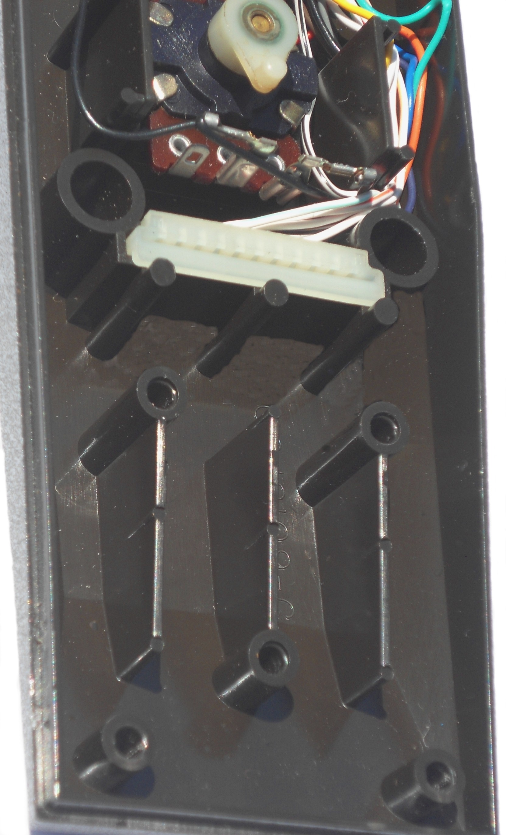
Left: Backside of the CX52 Joystick flex circuit support plate with 3 locating studs. Right: CX52 bottom case with 3 mating female bosses. Note the flex plate support long brown 3 studs next to the bottom edge of the white pinch connector bottom edge.
Best recommended procedure for installing the New Rev. 10 Gold flex circuit into CX52 Joystick bottom case.
1st it is best to try to remove off as much of the old adhesive or doubled sided clear tape off the CX52 joystick, left and right fire button right angle support plates and off the top 1/4 of the flex circuit support plate. Now this CX52 adhesive is close to 30+ years old and can be very difficult to remove.
An old Atari tech tip that can make this job a lot easier. Take a hair dryer set on medium heat setting. Example, heat up the flex circuit support plate top section where the old adhesive or adhesive strip is located. Heat up the old adhesive so it gets very hot to the touch or a gummy / sticky feeling again. Use a paper towel soaked in rubbing alcohol, you should find the old hot adhesive or adhesive strip is easily removed now.
The 3 adhesive strips on the backside of the Rev.10 flex circuit use a very strong adhesive. It is possible to remove / reposition them once they have been installed, but in some cases you can distort / bend the flex circuit Gold plated to back D shaped thin metal pads. So it best to consider the adhesive strips installation as one time procedure. It is a good idea to do a few dry runs (not removing the adhesive backing strip) and practice few times before starting the install procedure below, before removing the adhesive brown backing covers.
1. Install the preformed / pre-bent Best Rev. 10 flex circuit onto top side of the flex circuit support plate. Make sure the two locating tits (on the flex circuit support plate top surface) are within large Gold locating rings (with no distortions / wrinkles or excessive cone shapes in the 2 sounding Gold locating rings on the flex circuit).
2. On the backside of the Flex circuit support, note the triangular shaped brown locating (3) male pin pattern (see picture above). Also note the triangular shaped pattern (3) mating cylinders on the bottom of the CX52 bottom plastic case.
3. With a couple of fingers holding down the flex circuit on the support plate, lift the front edge of the flex circuit and remove the adhesive brown backing paper from the underside of the flex circuit. Gently push down on the flex circuit over the adhesive strip so the flex circuit is fully flat on the top of the support plate and adheres to the rounded top front edge of the flex circuit support plate.
4. Put the bottom edge of the Flex circuit floating sub assembly so the bottom edge is in parallel (about ½ inch floating above CX52 bottom case, just over the length of the 3 bottom locating flex plate studs) and even with bottom edge of the CX52 bottom case edge but floating in the air above the CX52 bottom case. In the CX52 bottom case, tuck the upside U shaped floating top flex circuit loop, into the CX52 bottom case, behind / under the Flex circuit support plate behind the 3 long brown studs (in the bottom CX52 case) that support the back side of the top edge of the circuit support plate.
5. Insert the left and right flex circuit arms into the bottom CX52 case. Next slide up the Flex circuit floating sub assembly so the top edge is just above the bottom edge of the white pinch connector edge. Insert the flex connecting strip into the white pinch connector opening. With 2 - 3 fingers gently push the connecting strip into the white pinch connector, so about half the length of the 11 Gold fingers it still exposed above the white pinch connector top surface.
6. Under the floating flex plate assembly, align the bottom flex plate 3 brown studs over the CX52 bottom case 3 female cylinders.
7. Gently insert the flex plate 3 studs onto the 3 female cylinders. As you are lowering the flex plate assembly into the CX52 bottom case, at the same time with your fingers gently push the top edge of the connecting strip until the connecting strip fully bottoms out, you will now find just a little of the tops 11 Gold fingers are still exposed above the white pinch connector top edge)
8. On either the left or right flex circuit fire button arms, note the bottom edge of the either fire button flex circuit location has a U shaped notch opening in it. Also note on either left or right fire button cavity, there is a mating molded in locating U shaped brown plastic stud, that the bottom edge of the flex circuit fire button arm open U shape notch fits into. Remove the brown adhesive paper backing on one of the fire button flex circuit arms. Angle the fire button flex circuit arm about a 10 to 20 degree angle out, so the bottom edge of the flex circuit arm is closes to the flex circuit cavity. Now align / seat the flex circuit fire button arm U shaped notch with mating brown plastic notch in the CX52 bottom fire button cavity. Now gently close up the angle so the flex circuit arm is now fully pressed / flat against the brown fire button right angle support plate. If you need to remove the attached flex circuit arm off the fire button support plate, it is best if you use a very thin metal or plastic device (like a credit card edge) with no shape edges on them. Gently angle back (5 to 10 degree angle) the top edge of flex circuit arm off the support plate. Use the thin edge to slowly push / wedge off flex circuit adhesive off the support plate.
Two locating circular round traces around the thru holes (to mate up the two location plastic tits on the flex circuit plastic support plate) on the numeric key pad section on the flex circuit have been widen and are now exposed (1st article samples had round thin trace circles were under the yellow solder mask (2 sides)) and now are Gold plated front and back sides of the Rev. 10 flex circuits. This requested charge was done to make locating the Flex plate locating tits easier to align on the flex circuit during flex circuit installation.
Left: Picture of the 1st article CX52 Rev. 10 flex circuit sample. Right: Picture 2nd article sample CX52 Rev.10 Flex circuit showing the 2 new Gold locating rings around the CX52 Flex circuit support plate 2 locating tits.
The brown stiffener tape behind the 11 finger section of the flex circuit was extend up / longer making installation of the Rev 10 flex circuit 11 pin connector strip much much easier to install push into white pinch connector (on the internal end of the CX52 cable assembly).
There were 3 different thickness stiffer samples that were installed on the 2nd article sample flex circuits for Best to run insertion and extraction tests on. Best approved the thickest stiffener tape sample. With the thickest stiffener tape, the thickness of the 11 finger section of the Rev. 10 Flex circuit when from .22 mm (1st Article FPC samples) to .42 mm thick. Compared to the last Atari Rev 9 flex circuit made 11 finger / connecting strip thickness of .16 mm. This means the new Best Rev. 10 flex circuit Gold finger thickness connecting strip is 2.6 times thicker compared to the last Atari rev. 9 flex circuits made.
2nd article Rev. 10 CX52 flex circuit front view.
This will apply about 2.6 times more internal pressure on the pinch connector metal contact fingers, thus preventing the unknown / hidden failure rate of the Rev. 9 flex circuit fingers losing contact (causing different CX52 Joystick function failures over the last 25+ years) with the metal pinch connector fingers with enough time (5 to 20+ years).
The requested pull tabs on the backside 3 adhesive pads / strip on the Rev 10 Flex circuit were added to all of the 2nd article samples. But after running some pull tests on them, Best felt the pull tabs were simply to small and not easily grab onto. Best asked our FPC manufacture increase the width, length and added a rounded edge to the end shape of three 3 pull tabs. We asked them to add 2 round radius were the pull tabs attached to the main body of the removable adhesive backing brown strips. Best felt the two sharp 90 degree angles on the 2nd article FPC sample brown pull strips were a possible tare point (the brown paper backing would tare into 1 or 2 pieces) when removing the brown adhesive backing paper.
On April 15, 2021 Best sent a 2nd Article receiving report back to our FPC manufacture approving the latest FPC samples. We requested the minor change to the 3 pull tabs. Also discussed on previous E-Mails with our FPC manufacture, Best requested they put in 4 pre-folds in the finished Rev. 10 Flex circuits to make installation of the much easier compared to the last Rev. flex circuits.

2nd article Rev. 10 CX52 Flex circuit with final bends in the flex circuit to make final installation a lot easier.
On April 30th 2021 Best sent the funds to our Manufacture to produce the Best Rev. 10 upgraded / Enhanced Atari 5200 flex circuits.

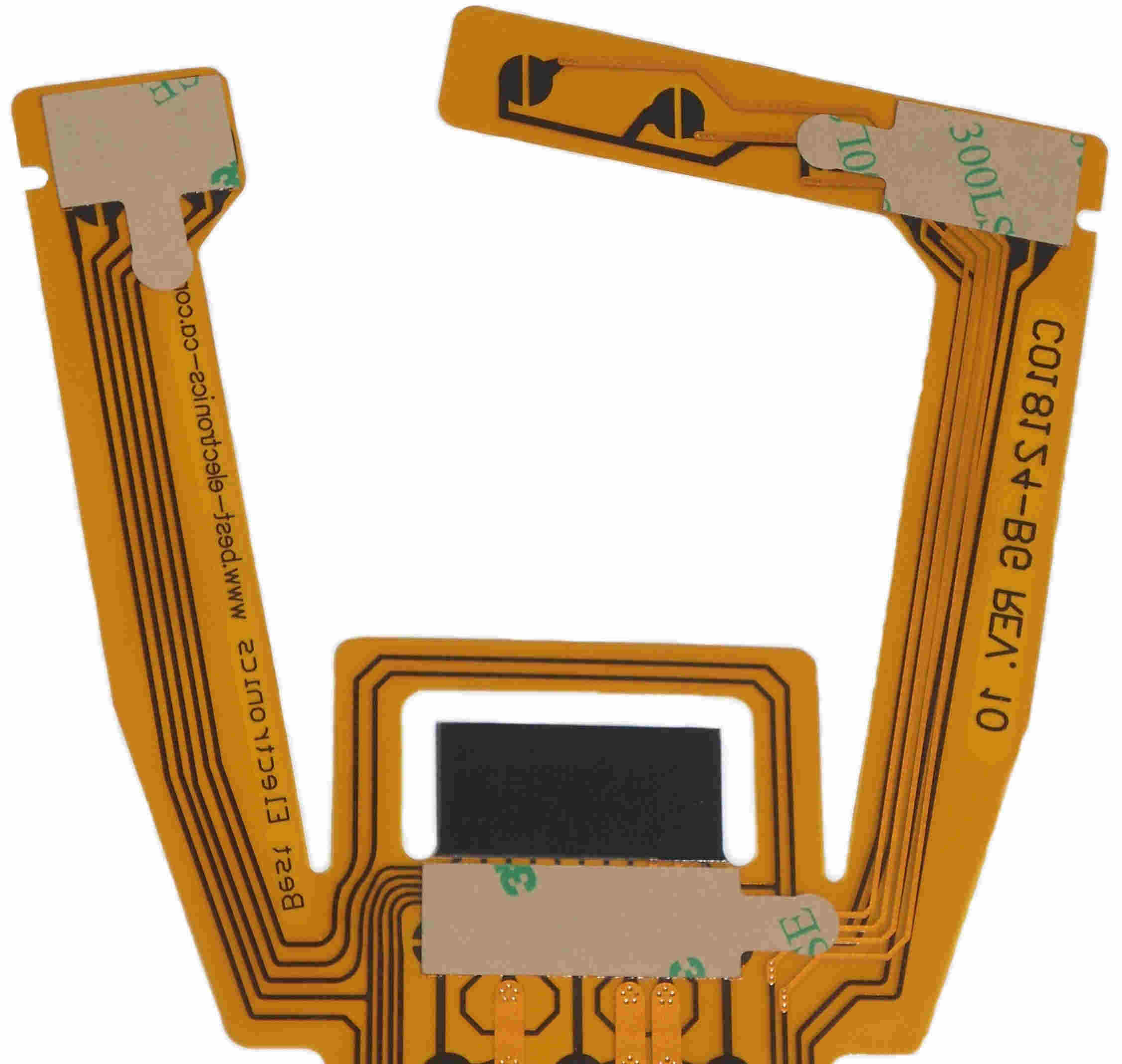
2nd article Rev. 10 CX52 flex circuit, backside, showing the 3 new requested adhesive brown paper backing small pull / removing tabs. Best judged the 3 pull tabs to be simply to small for the average adult to get a grip on them to remove brown backing paper. We requested on the final version Rev. 10 flex circuits these removing pull tabs were be enlarged.
Also notice that the dark brown stiffener tape height has been extended (compared to the 1st article samples) to make installation into the CX52 cable pinch connector a lot easier.
On May 24, 2021 we got an E-Mail in from our FPC manufacture saying that the 1st production run was just about complete. They said they will be able to send pictures to Best on May 25, 2021 of the final Rev. 10 Gold flex circuits for our final approval before sending the 1st small lot of them to Best.
May 25, 2021 Best received the 2 final pictures and approved them. The first group of the new Rev. 10 Best Gold flex circuits were shipped to Best.
1 of 2 Final pictures. Close up view of backside of Rev.
10 Flex circuit, showing the 3, 3M brand adhesive strips.
The requested extended / enlarged pull tabs with rounded
nose and 2 rounded corners at the base of the pull tab to
prevent the brown paper backing from tearing during the
removal process.
After 14+ months work on the Best CX52 Joystick Rev. 10 Upgraded / Enhanced Gold Flex circuits, on June 1, 2021 Best received the first shipment of them.
Add Best Electronics All Atari Web site to your Internet Explorer Favorites folder.
Copyright © 2002
Best Electronics in the Atari business since February 1, 1984.
This page Last modified: February 01, 2024
Back to Best Home page
Contact Information:
Our hours of operation are Monday through Friday 1:30pm to 5:00pm PST
(International Customers when
calling in to us, remember your local day may be a day ahead or behind us
depending on your location in the world.)

Current Pacific Standard Time is:
Telephone:
-
(408) 278-1070 (Hours above)
E-Mail: